Suppose you want to design a drawbridge as shown in the figure below. A cable runs from the end of the drawbridge to the top of a tower and then down to a heavy counterweight that rolls along a curved track. The counterweight makes it easier to raise and lower the bridge.

A natural question is: can we choose the weight and the shape of the curved track so the bridge and the weight are always in equilibrium? That is, when the bridge is in any position, it is neither pulled up by the counterweight nor down by gravity. Surprisingly, the answer is yes, and it involves one of my favorite curves: the cardioid.
First, let’s introduce some notation. As shown in the figure, we will assume the length of the bridge and the height of the tower are both 


Let’s first discuss the masses. When the bridge is down and the counterweight is at the top of the tower, the system should be in equilibrium. The drawbridge is a lever with a fulcrum at the tower’s base. The bridge produces a downward force of 


Hence, the counterweight’s mass must be

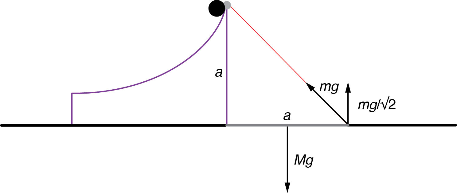
When the drawbridge is down, the length of the cable is 


Finally, saying that the system is always in equilibrium is the same as saying the potential energy is the same in every configuration. When the bridge is down, the counterweight holds all the potential energy, 


which simplifies to

A trigonometric identity gives us

When we combine the equations for cable length and potential energy by eliminating the 

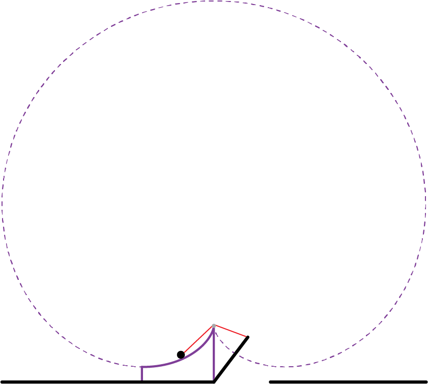
which is the polar equation for a cardioid! As we see in the figure below, the track is only a small portion of the cardioid curve (from 

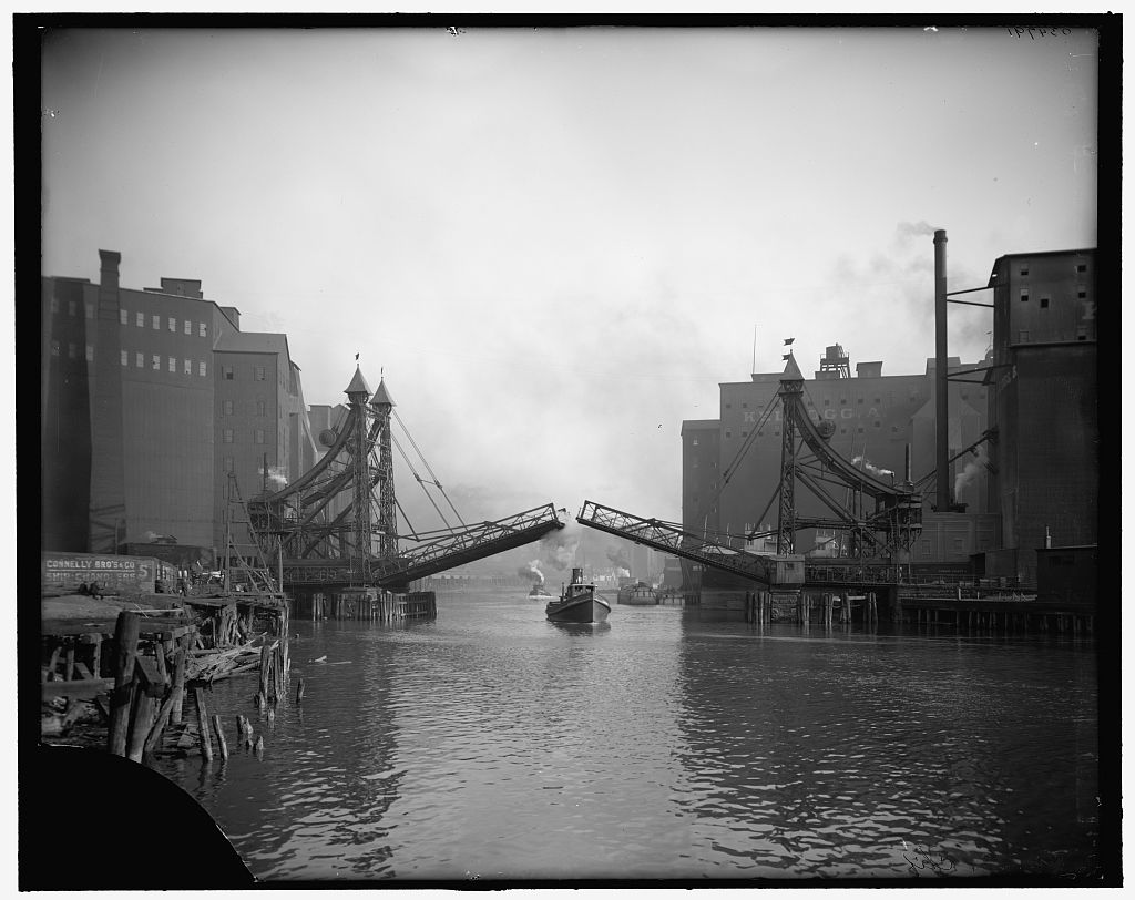
This design has been used around the world at various times. The bridge below is the Jackknife Bridge in Buffalo, New York. It was constructed in 1897, and this photo dates to 1900–1910. (Image source: Library of Congress)
The Glimmer Glass Bridge, located in Monmouth, New Jersey, is another such example. It was built in 1898 and was placed on the National Register of Historic Places in 2008. (Image source: Wikimedia)

This topic appeared in a pair of articles in the Mathematical Gazette in the 1990s. In 1990, H. Martyn Cundy wrote “The bascule bridge: An unexpected cardioid” (74 (468): 124–127). In 1995, Michael Deakin followed up with the much simpler argument I have expanded in this blog post (“More on bascule bridges.” 79 (484): 107–108).
