I am teaching an undergraduate course in topology. We are now looking at what we get if we take a square and glue the sides together. (These are called identification spaces.) We are assuming that our spaces are made out of very stretchy rubber. So, if the space begins as a square, we could, for instance, first stretch it out into a long rectangle before gluing. Stretching won’t change the topology.
As we see below, if we glue only the left and right sides together, we get either a cylinder or a Möbius band. (The arrows indicate which sides are glued together and with which orientations—we want the arrows to align when gluing.) If we glue pairs of neighboring sides together, we obtain a shape topologically equivalent to a sphere. If we glue opposite sides together without a twist, we get a donut-shaped surface called a torus. (Here’s a nice video showing this procedure.) The last two are trickier. In one, we glue two sides together without a twist as with a cylinder but we glue the other two sides together with a Möbius band-like twist. This shape cannot be made in 3-dimensional space regardless of how stretchy our rubber is. But if we let the surface pass through itself (or briefly “hop over” itself in the 4th dimension), we get a shape called a Klein bottle. (Here’s a video showing the procedure and here’s a website where you can purchase a glass Klein bottle). The last shape is by far the trickiest of them. In this case, both pairs of sides are glued together with Möbius band-like twists. The shape is called the real projective plane.

Like the Klein bottle, the projective plane can’t be created in 3-dimensional space. But whereas it is not too difficult to visualize the Klein bottle, the projective plane is much trickier to picture.
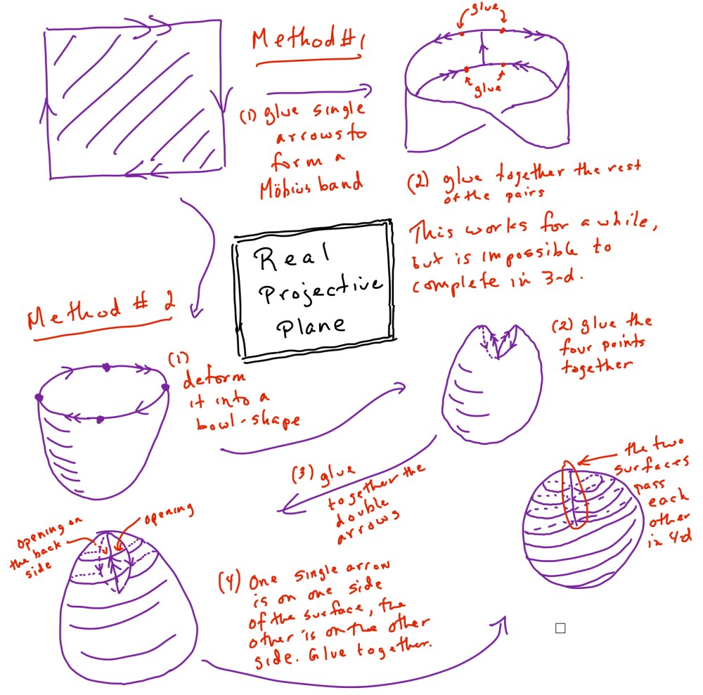
There are a number of equivalent ways of constructing the projective plane. We are viewing it as taking a topological disk (we could make our square round) and gluing together antipodal points—points opposite from each other on the boundary of the disk. (Another way is to take a Möbius band, which has one boundary curve, and glue a disk on to the boundary.)
Here is a sequence of steps I drew for my students.
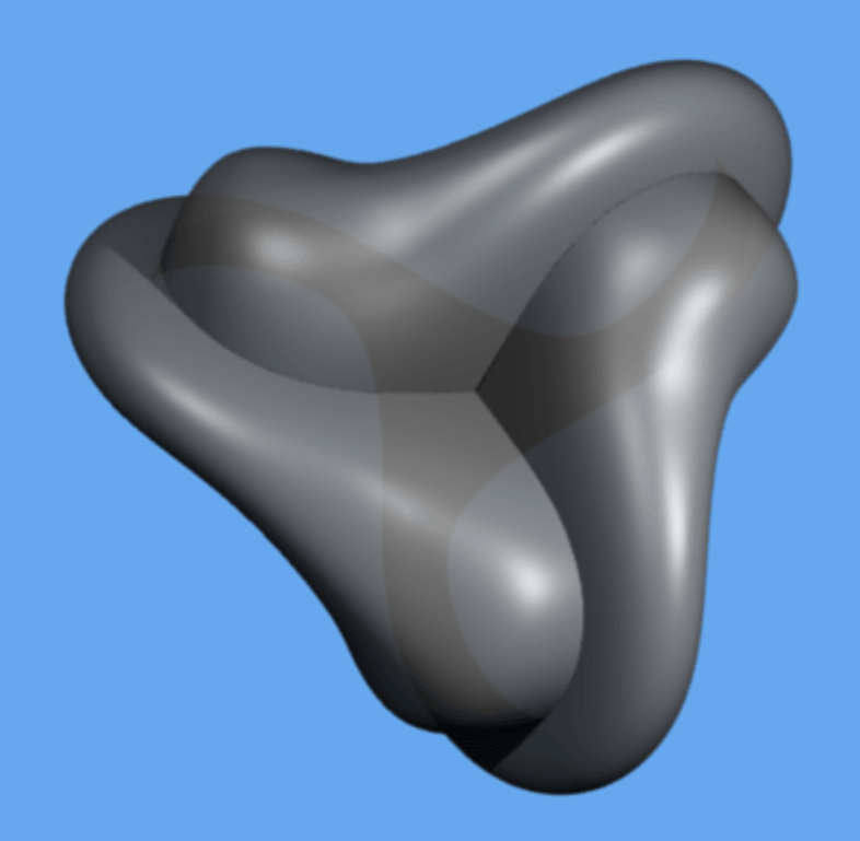
There are other ways to visualize the real projective plane. One is called Boy’s surface (it was discovered by David Hilbert’s student Werner Boy). Notice that it has self-intersections (in 3-dimensions) and one triple point—a point where three parts of the surface meet.
Here’s a video showing the construction of Boy’s surface. As beautiful as the video is, I still have a hard time visualizing what’s going on. In November 2007 Rob Kirby published this short item in the Notices of the American Mathematical Society in which he presented another way to visualize Boy’s surface. He presented Boy’s surface as a shape that can be made from three squares and four equilateral triangles. When I saw that, I knew I had to make it out of paper.
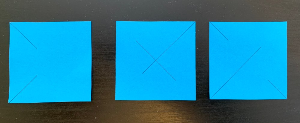
The first thing to observe in Kirby’s construction is that the three squares cross each other along their diagonals meeting at right angles. For instance, we could take the vertices of the squares to be the six points (±1,0,0), (0,±1,0), and (0,0,±1). They are the vertices of a regular octahedron. (Keep in mind that the three squares don’t actually meet along their diagonals—this is where they pass by each other in 4-dimensional space.)

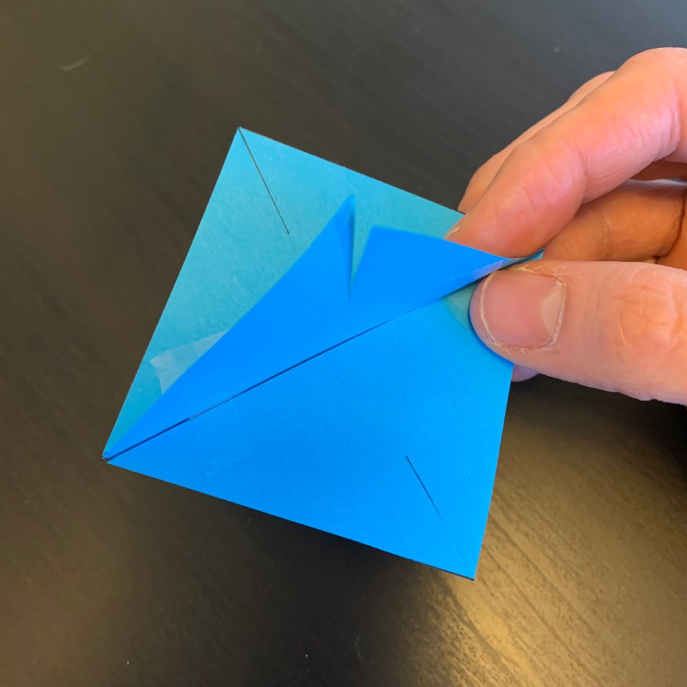
I realized that I could cut slits in my paper squares so that they would fit together in this pattern.
 The final step in the process is to tape the four equilateral triangles to this octahedral shape. There are eight openings in the octahedron and four paper triangles. Tape the triangles to every other opening. Said another way, no two triangles should meet edge-to-edge. They should meet only at their vertices. This is Boy’s surface.
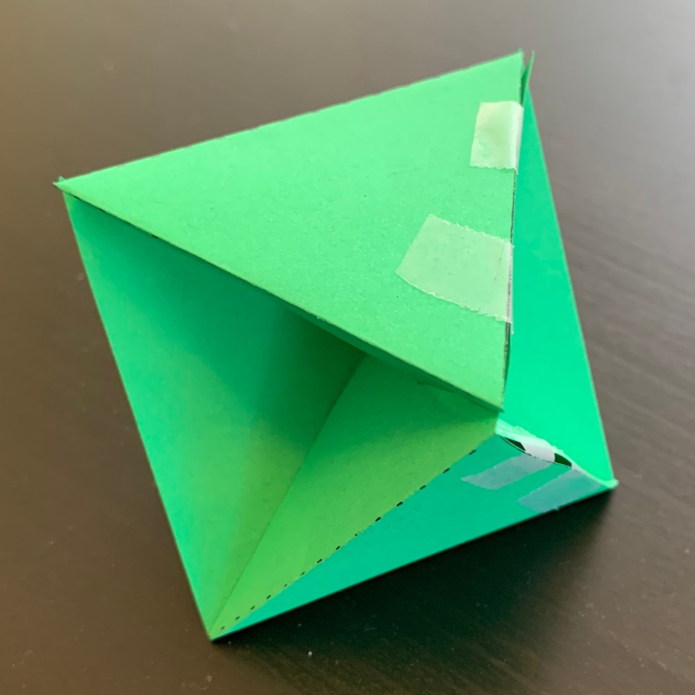
I made the following printable template (pdf) so you can make your own. [Update: the template now has tabs so you can glue the shape together if you want to.] It is a little tricky to get all of the pieces to fit together. The first step is to cut it out by cutting all of the solid lines. Then fold along the dashed lines (as mountain folds or valley folds as described on the template). The next step is to assemble the three squares as shown above. I recommend slotting together the 126 square with the central square first. Then do the 345 square second. Finally, tape the triangles. It should be obvious how to do this if you get to this point, but the numbers on the figure indicate what is glued to what (1 to 1, 2 to 2, and so on).
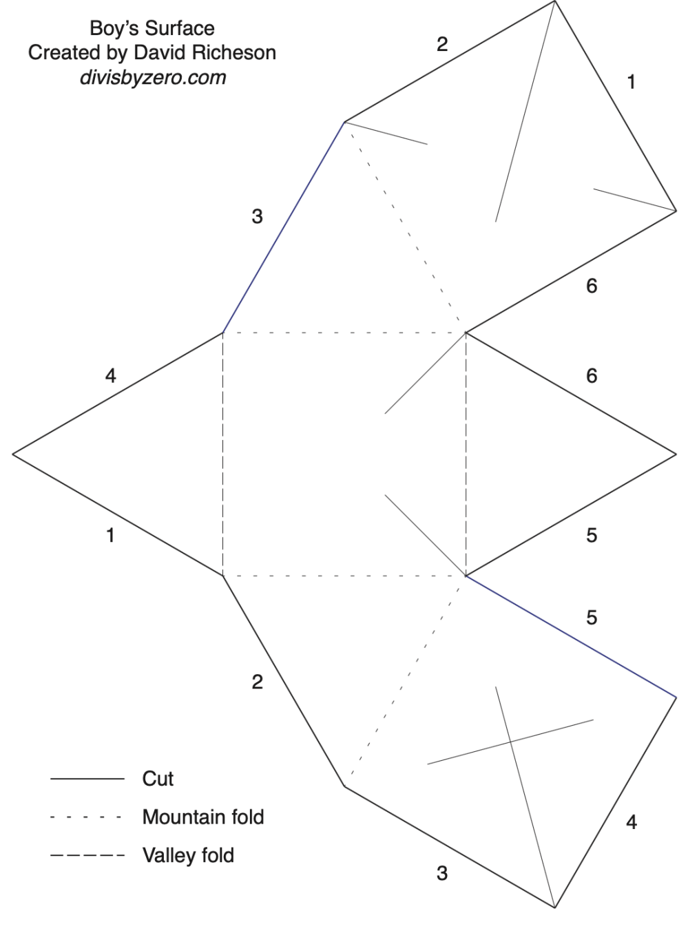
One question you may ask is: How can we see that this truly is the real projective plane? That is why I numbered the sides. First, notice that we could glue the two 5s together and the two 6s together. They are neighbors, so we are left with an eight-sided polygon with sides numbered 12341234. The key observation is that this numbering implies that we are going to glue opposite sides together on this polygon. In particular, we are gluing each boundary point to its “antipodal” point. That is exactly what we would do to generate the projective plane!
[Update: This shape happened to be on the cover of the November 2007 issue of the Notices. In the “About the Cover” blur, Bill Casselman mentions that the smoothed version of this shape is the Roman surface, another famous way to represent the real projective plane.]

One Comment
Comments are closed.