Several years ago I came across a fascinating application of graph theory to architecture. It is in the 1983 book Incidence and symmetry in design and architecture, by Jenny A. Baglivo and Jack E. Graver. I don’t know if it is well known among experts in the field, but I’ve never seen it elsewhere. So I thought I’d share it with all of you.
Here’s the simplest version of the problem. Suppose you have an 
Question. Where should you place the cross-beams, and what is the fewest number needed to stabilize the structure?
For example, consider the 

It turns out that the one on the left is rigid. In fact, it is over-braced; it can be braced with only eight cross-beams (we can remove the dotted beam shown in the figure below). The one on the right is not rigid, as can be seen below.

I encourage you to read the discussion by Baglivo and Graver, as they do a beautiful job of walking the reader through the problem. Here is a sketch of the argument.
1. In any bracing configuration (rigid or not) all of the vertical bars in a given row are parallel and all of the horizontal bars in a given column are parallel. You can see that in the deformed example on the right.
2. A cross-beam forces a parallelogram to be a square. By (1), if the square is in the ith row and jth column, then all of the vertical bars in the ith row are perpendicular to all of the horizontal bars in the jth column.
3. To have a rigid structure it suffices to show that the vertical bars in any row are perpendicular to the horizontal bars in any column.
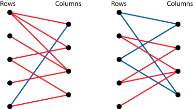
4. We can construct a bipartite graph from any bracing structure. In particular, we have vertices representing row numbers and vertices representing column numbers. We draw an edge from the vertex for the ith row to the vertex for the jth column if there is a cross-beam in the ith row and jth column. The graphs for our two structures are shown below.

5. Using property (2) repeatedly we find that if there is a path in the graph from the ith row to the jth column, then the vertical bars in the ith row are perpendicular to the horizontal bars in the jth column.
6. We conclude that property (3) holds (i.e., the structure is rigid) if and only if the bipartite graph is connected.
7. The smallest connected graph is a tree, and the the largest tree in the bipartite graph with 

Thus we have the following theorem.
Theorem. A bracing of an
Returning to our examples, we see that the graph on the left is connected, so that structure is rigid. In fact, we can remove one edge to obtain a tree, so the structure is over-braced. The graph on the right is not connected, so it is not rigid. However, we could add one more bracing to make it rigid (where?).
Again, I encourage you to check out the original source. They go on to discuss the following two related problems, both of which have graph theoretical solutions.
Question. What if we want the structure to be double-braced? That is, we want it to be rigid even if one of the cross-beams happens to fail (they allow cross-beams to form X’s in a square).
[You may not be surprised to learn that a tree in the bipartite graph is not sufficient—you need cycles.]
Question. What if the cross-beams are replaced by wires? The wires are not rigid (they can collapse), but they cannot stretch. How do you cross-brace your structure so that it is rigid?
[In this case you need to look at directed graphs.]

Very cool! Note, in the graph on the left you are missing the edge (3,2).
Thank you for noticing that! The graphs are fixed now.
Real architecture happens in 3D though. Is the graph theory still applicable somehow?
Regarding your question, the following link might be of interest:
Click to access seville.pdf